For many people BPMN is only about modelling process flows. However there are also elements, which allow you to show the data perspective: Data Objects.
They were one of the main topics of the BPMN Model Interchange Working Group demonstration in December 2018 in Seattle and will appear again in June 2019 demonstration in Amsterdam.
This is a long post, so below you can find navigation links:
A) Data Objects and Data Stores – a bit of theory
B) BPMN MIWG demo – Seattle 2018
C) More advanced aspects
D) BPMN MIWG demo – Amsterdam 2019
A) Data Objects and Data Stores – a bit of theory
Data Objects allow you to show data flowing through a process. Please note that this flow does not follow Sequence Flows, but Data Associations.
Technically speaking there are 4 elements representing data in BPMN specification: Data Object (plain), Data Input, Data Output and Data Store.
Data Objects may represent e.g. documents used in a process, both in physical and digital form. They look like a page with folded top right corner.

Important thing about plain Data Objects is that they are generally available as long as the process instance is live.
What does it mean in practice? Let’s assume you are working on a case of John Doe and need to process documents of this customer.
If you would add Data Object named “Customer request” it would represent document sent by John to your company. You could access it anytime while working on this case but NOT after you finish it.
To store information in a more permanent way you need Data Stores.
They are commonly used to represent IT systems and applications, but also plain old manila folders or archive would be suitable.
You can show how certain steps of a process use the data (either Data Objects or Data Stores) by using Data Association arrow (dotted line with arrowhead). Please note that token does not follow the Data Association – it is NOT a part of a process flow.

Last important thing is that you can define various states of the Data Objects. Those states are shown in a square brackets after a Data Object name. So we could have “Customer request [for analysis]”, “Customer request [analyzed]”, “Customer request [solved]” etc. You will see this in practice in section B below.
It is also possible to use a given Data Object (with the same name) several times in a process diagram in order to avoid drawing long Data Associations across the diagram. The same applies to Data Stores.
💡 Want to go deeper into BPMN? You can learn more about Data Objects and other elements of BPMN in my “BPMN for business analysts” course on Udemy.
B) BPMN MIWG demo – Seattle 2018
Below you can see more complex example of Data Objects usage taken from BPMN Model Interchange Working Group demo which took place in Seattle in December 2018.
You can learn more about BPMN MIWG, see recordings of past demos and test cases on our page: http://www.omgwiki.org/bpmn-miwg/doku.php
In case you are curious I also have posts with summaries of our 2015, 2016, and 2017 demos.
Now let’s take a look at an example process used in our 2018 demo.
You can click to open it in full resolution. It is also available for download (both as a graphic and BPMN file) from our test case repository (https://github.com/bpmn-miwg/bpmn-miwg-test-suite/tree/master/Reference) as C.5.0 test case.
BTW – below you can see original process from ADONIS example models which served as a starting point for the demo.
The process starts when a customer shows interest in a Bank’s offer. Front Office Account Manager needs to interview the customer and afterwards prove the customer identity.
This process steps creates Data Object “ID document” with a state “for analysis” (which you can see as “ID document [for analysis]” in a model).
Now there are several more process steps leading to Task “Check customer documents”. Original Data Object provides input for this task, which you can see by incoming Data Association.
Ideally completing this step would mean we do not need to perform any more analysis of the ID document, so the state changes to “ID document [analysed]”.
In case you are curious: technically speaking those two objects are Data Object References which share one common definition of the Data Object i.e. “ID document”, but have different states.
If you are feeling brave you can check this in a BPMN XML file 🙂
Our process continues and at some stage documents will be scanned leading to a third state for our Data Object (you can see it as “ID document [scanned]”).

As you can see above we can work with many Data Objects in a diagram. Since we already have the customer ID, most likely we would need to get some more data and perform the Know Your Customer activities required by law as well as some risk assessment.
This would introduce a new Data Object “Customer data” with states “for KYC analysis” and “for risk assessment”.
You may wonder – shouldn’t we have some record of the documents we are processing?
This is where Data Store comes handy 🙂 You can see that we added one called “Customer Data (temporary storage)” with lots of incoming Data Associations.
In order not to create something similar to spaghetti diagram you can have several references to the same Data Store in one diagram.
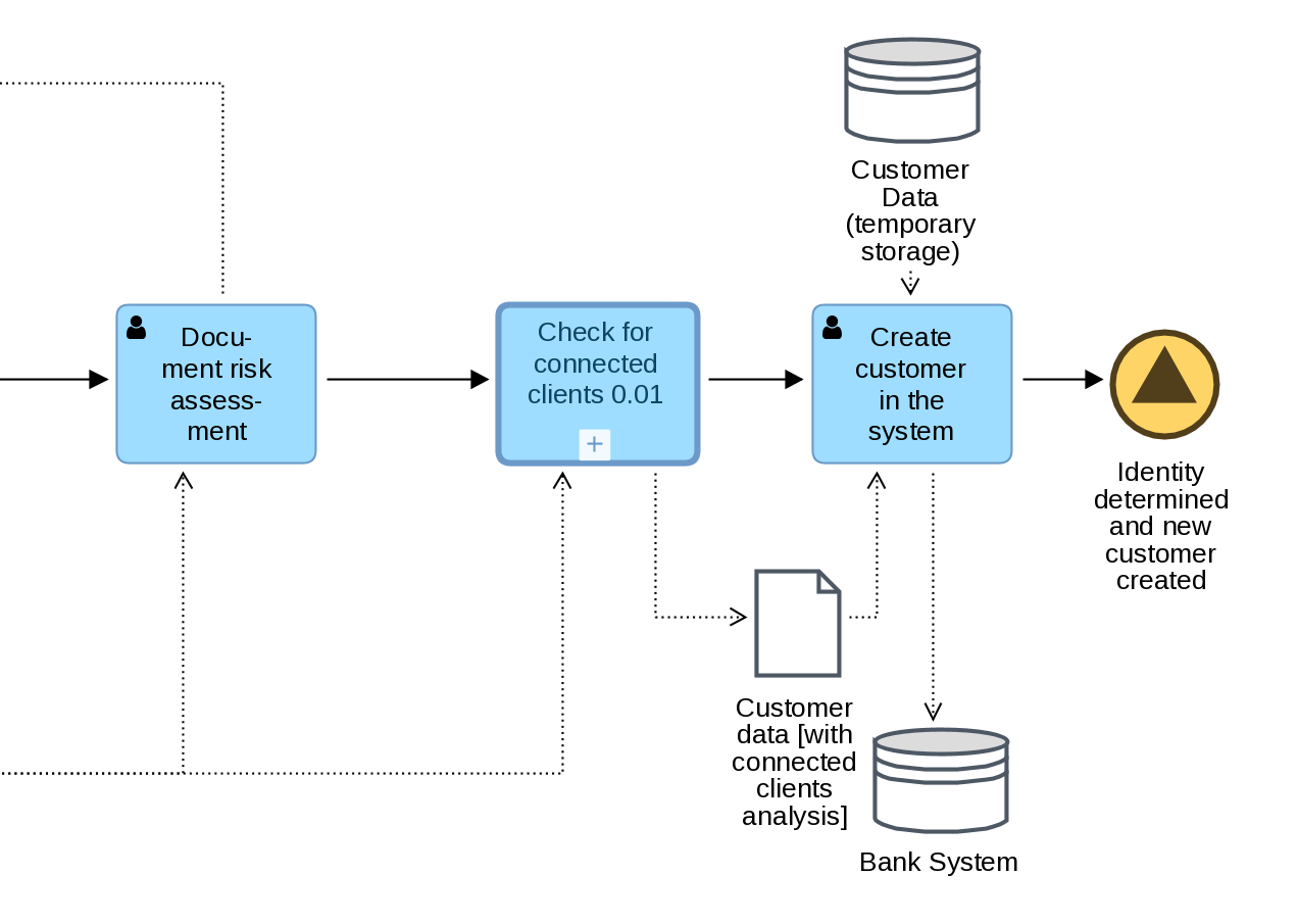
In the image above you can see the final part of the diagram where we finally create customer in a system. Info is taken from the clone of “Customer Data (temporary storage)” and moved to “Bank System” Data Store.
This way we could avoid having more Data Associations flowing through a process diagram.
Now it’s time to see how did our demo look like step by step.
As you can see from faces of participants, demo took place in a middle of the night for a majority of our group 🙂
At 1:45 Denis (chair of BPMN MIWG group) starts the session and participants present themselves.
As you can see from the further part of the demo, making 10 BPMN tools work smoothly together is a piece of cake in comparison with making Google Hangouts work with Windows 10 😉
At 10:04 you can see introduction of the diagram and general flow of the demo.
At 12:00 actual modelling begins. Alessandro starts modelling initial part of a process with BeePMN tool. At 12:20 JD follows with Enterprise Architect. As Denis noted – please remember that different tools have various interfaces and ways of modelling, but certain aspects of BPMN stay the same (e.g. User Tasks are always rounded rectangles with a person icon in a top left corner, Exclusive Gateways are diamonds with X inside etc.).
At 13:25 Denis gives you introduction to the concept of reusing Data Objects with Data Object references as well as a lifecycle.
I’m joining at 14:59 in order to take over diagram started by Alessandro. As you can see I am using browser based ADONIS for this purpose. Since we all have tools supporting the concept of BPMN Diagram Interchange it is sufficient to import a BPMN file to have everything ready for further work.
At 15:28 Timothy from Signavio joins and starts modelling additional part of the diagram.
At 15:37 Simon from Trisotech appears in order to start stitching the ready pieces together.
Are you wondering why there’s so much switching between the tools? Our first demonstrations were more sequential, but with 10+ tools and 30 minutes for a presentation we had to come up with a way not to bore participants to death by creating trivial diagrams step by step. That’s why some steps are happening at the same time. Denis helped all the participants by providing narration of what was happening.
At 17:19 both parts are ready and both ADONIS and Signavio export their diagrams to our shared Dropbox, so that Simon can take them.
In the mean time at 17:35 you can see François from ITESOFT.
Simon continues his work at 17:51 and joins the diagrams. Please note how Data Associations show the data flow across the process.
As Denis noted there are various tools participating in the demo. This year browser based tools were clear majority.
Falko from Camunda joins at 20:21 to take over a Phase 1 diagram prepared by Simon.
While Falko is modelling Denis answers questions about formats used for BPMN Diagram Interchange. In short: XML is the best option, XMI is rarely supported and JSON is not supported in BPMN specification as interchange format.
Boris from CaseAgile joins at 21:50 to create his part of the diagram. Please note that Boris uses Enterprise Composer which is an add-on for Visio providing support for BPMN Diagram Interchange (since Visio allows BPMN modelling but does not allow import and export of BPMN DI files out of the box).
Frank from Software AG (with ARIS tool) joins at 22:50 in order to create a new diagram (“Check for connected clients”) which will be linked with a main diagram via Call Activity.
By the way – this diagram did not use any Data Objects, but it should be noted that Data Objects have interesting accessibility. If you have a Data Object in a top level process it can be accessed by this process, all tasks and Sub-Processes inside it. However if you define a Data Object in a Sub-Process it will be accessible for this Sub-Process and elements inside it (e.g. Tasks) but NOT by a higher level process. You could say that children can access Data Objects of their parents, but parents cannot access Data Objects of their children or grandchildren 😉
Please note that in our demo we did not use any Data Objects in a sub-diagrams. It is however possible to access Data Objects from various process levels. This is discussed in part C of the post.
At 24:56 Tim from KnowProcess joins with OmnyLink tool (based on Activiti BPMN engine). Please note that this is a first BPMS tool (automation engine or workflow tool if you prefer the older name) in the demo. This time we did not have time to finish demo with actual execution of the diagram, but you can watch our previous demos to see how did it look like.
Tim’s part shows in a nice way how you can define many states for the same Data Object (in this case we have Customer Data with state “for risk assessment”).
François joins again at 28:52 with BPMN+ tool to import diagram created so far. Fun fact – while BPMN does not specify colors for diagram elements there is an extension proposed at MIWG: BPMN in Color which allows to interchange colors of BPMN shapes. You can see the results in this part as some of the elements have colors as defined in previous tools.
You can also see how it is possible to add more technical (hidden) attributes for e.g. Signal End Events.
As Denis stresses it is very important that BPMN standard allows users to pick tools they like and smoothly exchange BPMN diagrams with others, even if they are using totally different tools. BPMN DI prevents vendor lock in and gives users more flexibility.
Since all the parts are available now Simon can start joining everything (at 33:10). During this time (at 34:20) Denis tells more about colors in BPMN which I covered above.
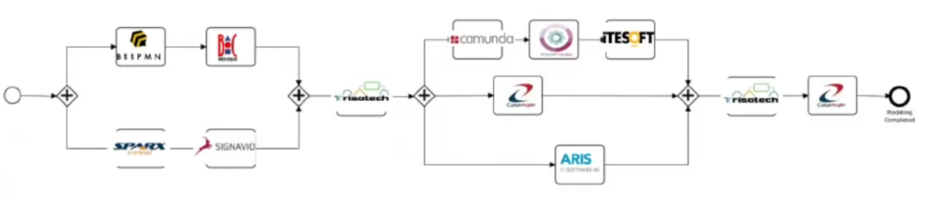
At 35:31 you can see in practice that all the elements referring to data which were added during the demo were calling 2 common definitions of Data Objects: ID document and Customer data. You can also see two Data Stores.
At 36:30 you can see how Boris uses other tool (BPMN View) to show the final version of a diagram prepared by Simon.
Finally after summary provided by Denis demo ends.
But is it everything you can do with Data Objects? Keep reading…
C) More advances aspects
Apart from the elements you could see so far there are also several more aspects of handling data in BPMN diagrams.
But before we go any further I want to give you a warning. Data Objects (especially in more advanced forms) are not very commonly used in BPMN.
As I learned from colleagues involved in BPMN specification preparation idea behind Data Objects was that they will be facilitating process automation. From my experience however I see them rather as documentation elements since some automation vendors do not use them in execution, while other tools even remove them at import. This does not mean of course you cannot use them for your process documentation 🙂
Now, it’s time to tackle more advanced elements.
Data Inputs allow you to show what kind of data is needed by Processes, Sub-Processes and Tasks in order to execute, so they are the data requirements. Data Outputs are on the other hand showing data produced by Processes.
They look very similar to the plain Data Objects, but have arrow marker.
Data Inputs have unfilled arrow:

Data Outputs have filled arrow:

Interesting fact is that Data Inputs show what are the inputs to the process so e.g. info from preceding processes and Data Outputs show the outputs of the process which can feed the following processes.
You will see example of this in section D where process for our 2019 demo is shown.
By the way – there are much more technical aspects, but they are mostly hidden attributes.
Now the last element. So far we assumed that we have one “document” every time i.e. one ID, one customer documentation etc. However it is possible that in your process you need to handle whole set of documents like e.g. batch of invoices or order with many positions.
If you want to show this, you can mark the Data Object as a collection. It will get a marker you know from Multi Instance Tasks.

D) BPMN MIWG demo – Amsterdam 2019
As I wrote above, we will be handling Data Inputs, Data Outputs and more during next BPMN MIWG public demo, which will take place in June 2019 in Amsterdam. Stay tuned for more updates!
In the mean time please take a look at our diagram.
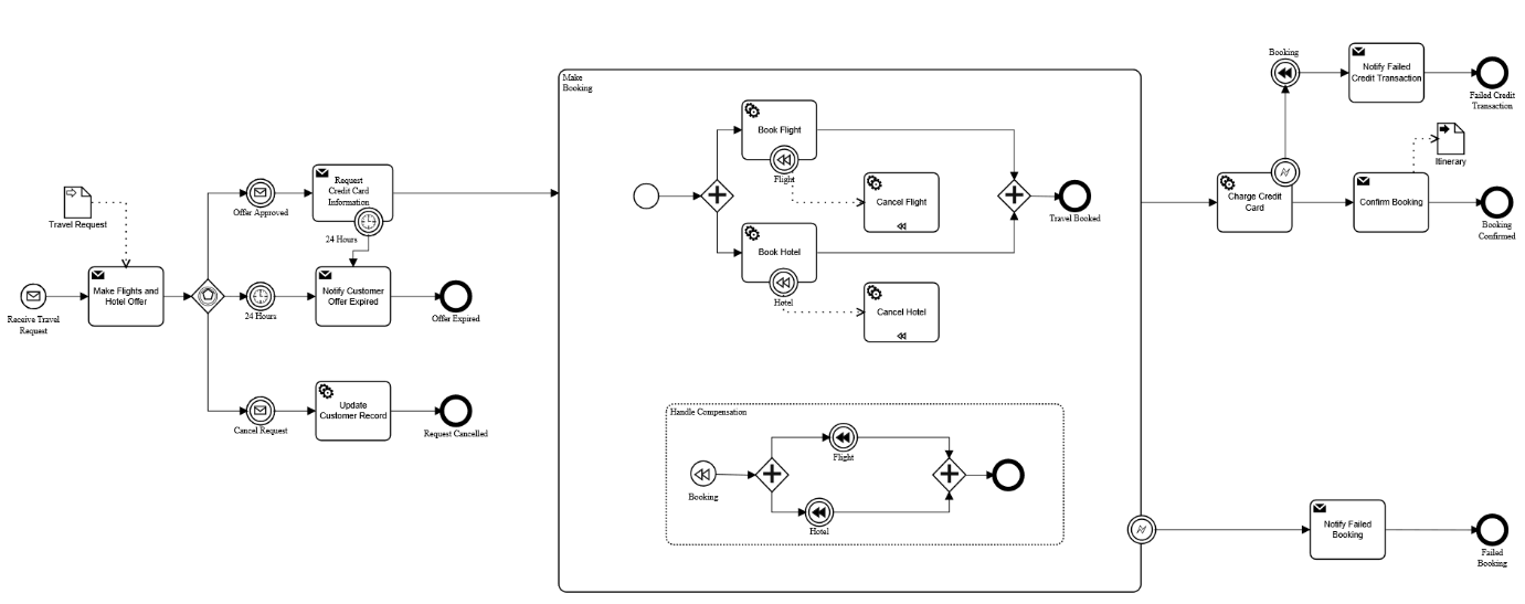
As you can see Data Input for our process is a Travel Request. After everything was done, Itinerary is produced as a Data Output of the process.
Do you want to learn more about process modeling with BPMN? Take a look at my course “BPMN for business analysts” on Udemy.
Thank you and very informative. Exactly what I was looking for to understand how the existing BPMN processes we have could be augmented with a data perspective